Journal of Biomedical Engineering and Biosciences (JBEB)
ISSN: 2564-4998

Volume 4 - Year 2017 - Pages 34 - 42
DOI: 10.11159/jbeb.2017.004
Development of a Porcine FE Model for the Investigation of Vertebral Laminae Strains Resulting From Facet Tropism
Colin Bright1, Stephen Tiernan1, Fiona McEvoy1, Pat Kiely2
1 Institute of Technology Tallaght
Tallaght, Dublin 24, Ireland
ColinBright@ittd.ie; Stephen.Tiernan@ittdublin.ie; Fiona.McEvoy@ittdublin.ie
2 Our Lady’s Children’s Hospital
Crumlin, Dublin, Ireland
Abstract - As many as 85% of adults experience back pain that interferes with their work and leisure activities, and 25% of people between the ages of 30–50 years report lower back symptoms. Much of the pain and discomfort in later life results from an untreated condition during adolescence. Stress fractures of the vertebral lumbar laminae are given the clinical name spondylolysis. This vertebral defect is an acquired fracture with 7% prevalence in the paediatric population. This fracture has a mechanical aetiology, and fair evidence exists to support the role of facet tropism (geometric asymmetry) as a predisposing factor. Tests were carried out on porcine lumbar vertebrae, on which a series of angular asymmetries were simulated. Strain was recorded using 3-element stacked rosette strain gauges placed on the vertebral laminae. These tests showed that as each subsequent step of asymmetry is applied there is an increase in both Von Mises stress and strain on the ipsilateral side, this increase has a complex non-linear progression and pathological values for strain (>3000µε) are recorded indicating potential damage, which is supported by an average 17% reduction in facet/laminae stiffness (N/mm). An FEA model of the vertebra was created using µCT scans and published formulae linking bone mineralisation to material properties. This model successfully replicated both the facet/laminae stiffness (N/mm) and strains that were measured during test. The degree to which facet asymmetry is a predisposing factor and the knowledge of potentially pathological strain levels in the vertebra are important parameters when evaluating new implant devices and surgical techniques.
Keywords: Spine, Fracture, Spondylolysis, FEA, Bone mechanics
© Copyright 2017 Authors This is an Open Access article published under the Creative Commons Attribution License terms. Unrestricted use, distribution, and reproduction in any medium are permitted, provided the original work is properly cited.
Date Received: 2014-09-18
Date Accepted: 2017-03-14
Date Published: 2017-09-13
1. Background
1.1. Introduction
As many as 85% of adults experience back pain that interferes with their work and leisure activities, and 25% of people between the ages of 30–50 years report lower back pain symptoms [1]. Vertebral stress fractures in otherwise healthy, athletic adolescents are a well-documented problem [2] [3] [4] [5]. The neural arch of the lumbar vertebrae, specifically the portion between the articular facets, known as the pars interarticularis, is particularly susceptible. Stress fractures in this region are given the clinical name spondylolysis. This vertebral defect is an acquired fracture with a 7% prevalence in the paediatric (<18 years old) population, however, this number increases in the athletically active population with up to 11% of female gymnasts [6], 10.5% of Swedish athletes [7] and 10.7% of Canadian gymnasts (>10 years old) [8]. It can occur unilaterally which ordinarily leads to healing, or bilaterally, which in chronic cases can lead to grade 1 or 2 spondylolisthesis (anterior displacement of the vertebral body) [9]. The fracture occurs at the lowest lumbar level in 90% of cases and fair evidence exists that paediatric patients with spondylolysis will develop significant lumbar symptoms in later life [10].
While a considerable volume of work exists on the links between athletic technique and spondylolysis [11] [12] [13], particularly among athletes who participate in hyperextension sports where a prevalence of 21% of spondylolysis has been recorded [14], the role of the underlying bony anatomy remains unclear. It is clear from the increase in prevalence between the normal paediatric population and those that are athletically active that the fracture has a mechanical aetiology, and evidence exists to support the role of facet tropism as a predisposing factor [15], particularly those with a more coronal orientation of one facet joint [16] [10].
The pars interarticularis is loaded when a bending force created by extension of the spine in the sagittal plane is transmitted to the facet joints. The force inducing this bending is applied perpendicular to the principal axis of the pars, on a plane which is 30˚ from the mid-plane of the intervertebral disc. In this plane, the extensor force can be divided between the left and right hand facet joints. If one of these facet joints is more coronally orientated the portion of extensor force on that side will be increased, thus the force acting in the posterior direction on that side will be greater than the less coronally orientated side. The research question under investigation is that if this difference in coronal orientation of the facets causes a difference in facet loading, is a difference in strain created between the left and right pars interarticularis? And can this difference in strain be replicated with an FE model developed from µCT scans.
1.2. Related Work
The assessment of strain in bones is best achieved by measuring the bone surface deformation. The use of bonded resistance strain gauges is a well-established method for taking these measurements [17] [18] [19] [20]. To date only a moderate amount of attention has been given to the measurement of strain in the posterior portions of the vertebrae. The most significant work done to date is that of Shah [21] where function spinal units (FSU) from human cadavers were fitted with rosette strain gauges and loaded in tension and compression. The authors measured strain on the ventral and dorsal surfaces of the pars interarticularis at a compressive load of 1472 N applied to the entire FSU which resulted in a dominance of tensile principal strain on the ventral surface of the pars, and compressive principal strain on the dorsal surface, indicating that the pars interarticularis itself is undergoing bending. Recorded values for compressive principal strain on the dorsal surface were between 2400µε and 2450µε. Sawa et al. [22], in an in-vitro study of facet loads calculated using strain measurements, reported facet loads of 75.4 ± 39 N in full spinal extension where bending moments of 7.5Nm were applied to T12-L2 spinal segments with 400N follower load. Szivek [23], studied the in vivo strains on lower thoracic vertebral laminae with biologically bonded strain gauges reported maximum strains in the vertebral laminae during twisting. Values from 495 – 1450µε were reported over a period of weeks, increasing as the calcium phosphate coated gauges became fully bonded to the bone surface. The highest laminae strain values were reported during stair climbing at 1795µε. Kuo [24] in a study of porcine pars interarticularis strains during swaying motions, stated that strains were highest (≤ 1700 µε ) during motions in the posterior and posterolateral directions (extensions of the spine with twisting). This lends support to the hypothesis that like the physical motion of twisting the asymmetric bony anatomy causes twisting and the strains on one side of the pars interarticularis are increased.
Bone tissue is known to behave differently depending on strain level. The strain level and local strain history dictate the cellular response [25]. The fracture under investigation in this study is known to be a fatigue fracture, that is, a fracture which has occurred due to cyclical application of load. This cyclical loading action leads to a strain concentration around a geometric feature and the initiation of a crack which grows with each successive application of load. As with any engineering fatigue problem, the loads applied typically lead to stresses well within the yield values. The expected strains in this study should fall close to, or below the pathological level (< 3000µε) [26]. It is typically the presence of a stress raiser, flaw or some other pre-disposing factor along with the cyclical application of the load that creates the initial crack; in this case the predisposing factor is hypothesised to be geometric (bony) asymmetry.
The availability of suitable human specimens, particularly from the young population poses a significant challenge. Many researchers therefore use animal specimens, with advantages being the homogeneity of specimen, plentiful supply and the avoidance of harmful pathogens associated with un-embalmed human cadavers [27] [28] [29]. Popular alternatives to human specimens are rusine, ovine, bovine [30] and porcine [31] [32]. The choice of porcine specimens for this study, and particularly those from animals of 6 months old is further supported by the fact that they represent an immature skeleton, such as that of a paediatric patient. The 6 month old porcine vertebrae are at a transitional stage of strength development from a bone density dominant strength to a structural anisotropy strength dominance [33].
2. Materials and Methods
2.1. Specimens
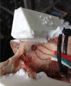
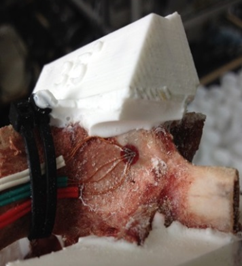
For this study, porcine lumbar vertebrae were selected, the 4th lumbar vertebra from 3 different 6 month old animals. Specimens were labelled S1, S2 and S3 with weights of 60kg, 62kg and 85kg respectively. The vertebrae were dissected of all soft tissue then cleaned using a scalpel. Two TML 45˚ /90˚ 3-Element Stacked Rosette gauges (∅ 4.5mm) were fitted, one each on the right hand and left hand vertebral lamina (Figure 3 & Figure 4). Before fitting, the bone surface was prepared by cleaning with grade 400 sandpaper; the bone was then degreased using Vishay GC-6 isopropyl alcohol. The gauges were fitted using cyanoacrylate adhesive (TML).
2.2. Experimental Method
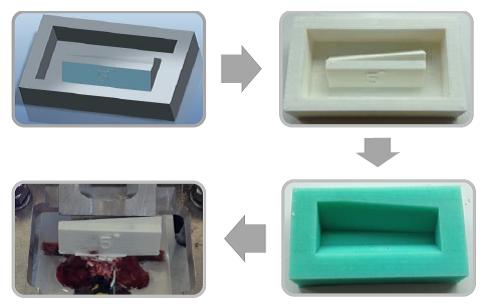
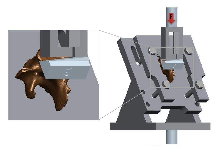
A series of angular asymmetries were simulated by casting a polymer resin (Smooth Cast 300) around the inferior articular facet surfaces (Figure 1). Angles were cast at zero degrees, 1.5˚, 2.5˚, 3.5˚ and 5.0˚. Casting molds were produced by first creating a 3D model of the desired part in a commercial 3D modelling software (Creo); this model was then printed using an additive manufacturing process (Makerbot Replicator). From this printed plastic mold a flexible silicone (Mold Max 40) mold negative was produced which in turn was used to cast the polymer resin around the bone. The superior end of the vertebral body and superior facets were also fixed in a casting resin before the specimen was placed in the test apparatus (Figure 2). The apparatus was manufactured to hold the vertebrae such that the force acting on the facets was equivalent to the resistance to anterior slippage along a plane through the L4-L5 intervertebral disc.
This force is comprised of the mass of the body above the L4-L5 intervertebral disc acting with gravity along this plane. The apparatus design was an adaptation of that used by Cyron et al. [34]. Tests to failure carried out as a precursor to this study established an average ultimate failure load of 1600N (based on 5 lumbar porcine specimens). Half of the ultimate failure load was chosen as a suitable test load for repetitive tests on each specimen without the risk of failure [35], in this case 800N. The apparatus was mounted in an MTS Bionix servo hydraulic test machine; the machine was programmed to initially apply 250N and unload to zero Newton’s as a pre-conditioning cycle, before applying the full test load (800N) at a rate of 0.2mm/s.
2.3. Finite Element Analysis
The finite element model was developed by taking both geometry and material property information from micro CT scans of a porcine 4th lumbar vertebra. The vertebra was scanned using a Scanco Medical µCT 100 scanner, power 55kV; resolution 73.6µm. Scan images were stored as 16bit DICOM files. Scanner calibration was carried out using a hydroxyapatite phantom allowing equivalent density values to be related to 16bit grey values using Equation 1 below.

Young’s Modulus for bone tissue (Et) in GPa was calculated using the published formula of Wagner [36] (Equation 2).
Solutions to Equation 2 depend on 3 input values, the densities of the 2
constituents of the bone matrix, mineralised bone (![]() ), collagen (
), collagen (![]() ), and the volume fraction (
), and the volume fraction (![]() ) of organic material (collagen). In this case the
density of mineralised bone is taken as the equivalent density of the
hydroxyapatite phantom used to calibrate the micro CT scanner, this number
varies throughout the specimen with the degree of bone mineralisation. The
remaining 2 values are fixed; the organic volume fraction is taken from the
Wagner study and represents the lowest volume fraction of organic material. The
density of organic material differs to that used in the Wagner study, as their
study was based on human bone, instead a value was used from the porcine bone
matrix density study of Cao [37]. From these
equations a table of material property data was calculated and presented in
.xml format for use with the CT scan segmentation software. The calculated
values for Young’s modulus were in good agreement with the values for porcine
cortical bone (10 – 15GPa) measured by Feng [38].
) of organic material (collagen). In this case the
density of mineralised bone is taken as the equivalent density of the
hydroxyapatite phantom used to calibrate the micro CT scanner, this number
varies throughout the specimen with the degree of bone mineralisation. The
remaining 2 values are fixed; the organic volume fraction is taken from the
Wagner study and represents the lowest volume fraction of organic material. The
density of organic material differs to that used in the Wagner study, as their
study was based on human bone, instead a value was used from the porcine bone
matrix density study of Cao [37]. From these
equations a table of material property data was calculated and presented in
.xml format for use with the CT scan segmentation software. The calculated
values for Young’s modulus were in good agreement with the values for porcine
cortical bone (10 – 15GPa) measured by Feng [38].
Young’s Modulus for bone tissue (Et):

Where:
- 004_files/image004.gif = Density of Hydroxyapatite [g/cm3]
- 004_files/image005.gif = Organics (collagen) Density [g/cm3]
- 004_files/image006.gif = Organics Volume Fraction
The CT scan data, in DICOM format, was analysed using segmentation software (Materialise, Luven, Belgium) and from this a geometry file was created and subsequently meshed. The material property table was used to assign material properties to each tetrahedral element based on the DICOM grey values contained within each meshed volume. The cast polymer mounting pieces mentioned in the experimental method section above were then integrated into the vertebra model using Boolean subtraction tools. The entire assembly was then exported to a commercial finite element modelling package (Ansys) for analysis. There were 193799 tetrahedral elements in the vertebra model.
The workflow from experimental to FE model is as follows:
- Experimental tests were carried out on porcine specimens for each level of asymmetry
- Displacements were recorded at maximum load for each level of asymmetry
- The recorded displacements were then applied in the FE environment
- FE strains were recorded
3. Results
3.1. Static Force vs. Displacement Tests
The static stiffness (N/mm) of each specimen was measured at zero degrees of asymmetry in order to establish a baseline for comparison of results. Specimen’s S1, S2 and S3 were tested with values of 903N/mm, 976N/mm and 838N/mm respectively. Of particular interest was the stiffness value for the specimen that was used for µCT scanning, this correlated very well (0.96% difference) with the value found in FEA (894N/mm).
3.2. Principal Strain Results
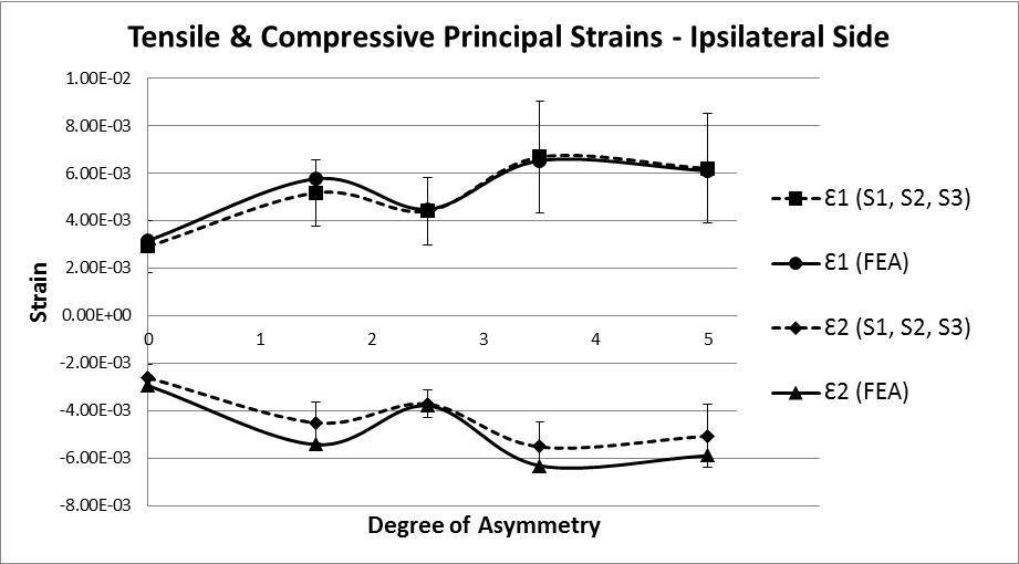
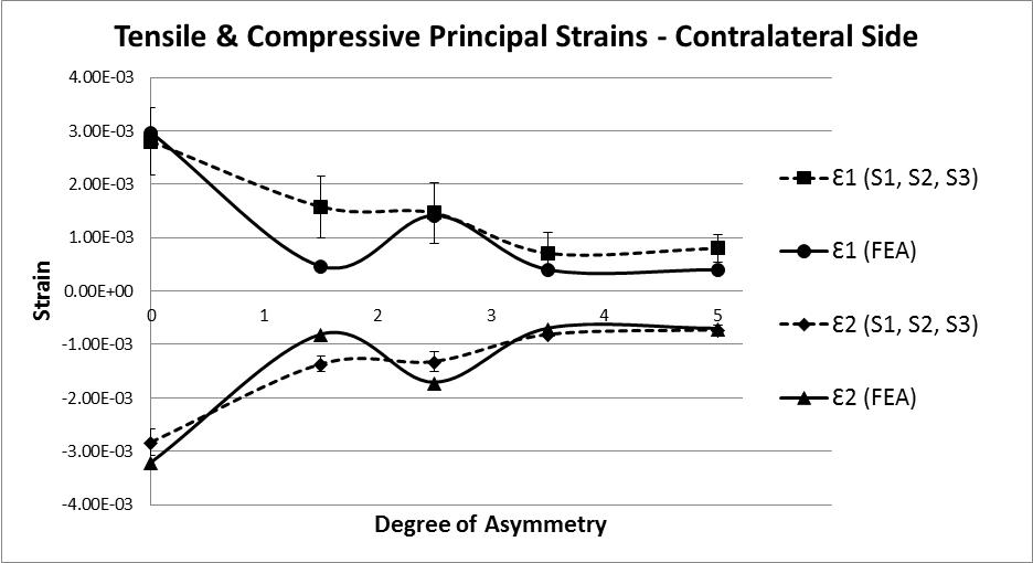
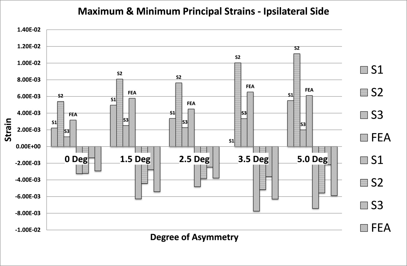
The analysis of strain results focusses on the ipsilateral side of loading. This is the side on which the results of the increasing asymmetry are most evident. Figure 5 shows a comparison of tensile and compressive principal strains on the ipsilateral side, averaged across 3 specimens, increasing in magnitude as the degree of asymmetry increases, conversely Figure 6for the contralateral side shows a decrease in strain magnitude. These figures show excellent agreement between FE predictions and test results, on the ipsilateral side with 5% average error, and fair agreement on the contralateral side with 40% average error. What is clear from the data is that as the degree of asymmetry increases, so the resulting principal strains increase on the ipsilateral side. Figure 7 shows the ipsilateral principal strain data from all tests, including FEA.
4. Discussion
4.1. Specimen Facet/Laminae Young’s Modulus Strain Asymmetry
Bone density is a measurement of the degree of mineralisation within a given volume of bone and is known to correlate strongly with bone strength [39] [40]. Porcine bone is known to be up to 30% greater in terms of density [32], studies by the World Health Organisation [41] Indicate an average human bone density of 1.2 g/cm3. The average calculated density for this porcine study is 1.28 g/cm3; using the formula of Wagner (Equation 2) these density values return tissue Young’s Modulus values of 1GPa and 7GPa respectively. This is not intended to be used as a scale factor, simply an observation of how differing average bone density values can affect specimen Young’s Modulus.
The force vs. displacement tests carried out at the beginning of the study were repeated at the end to explore the possibility that the specimens had been damaged, and although no external damage was visible on any specimen, the data suggested that yielding may have occurred internally. Specimen S1 showed a 39% reduction in facet/laminae stiffness (N/mm), specimen S2 showed 26% reduction in facet/laminae stiffness (N/mm), specimen S3 was unchanged. Specimen S1 showed the greatest reduction, this was due to the unavoidable drying during µCT scanning and the associated additional freeze-thaw cycles, this process reduces the elastic effect of the collagen and makes the vertebra more brittle and although initially stiffer more susceptible to damage in the longer term. Specimen S3 suffered no reduction in facet/laminae stiffness; this vertebra came from an animal that was 40% heavier and the vertebra itself was more elongated (anterior to posterior) which leads to a different apportionment of stress.
4.2. Strain Asymmetry
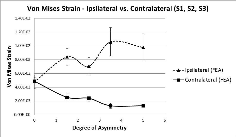
The hypothesis under investigation is whether facet tropism, or geometric asymmetry, causes an asymmetry of loading in the vertebral laminae, and if so, to what degree. The data suggests that as asymmetry increases the level of strain in the bone increases, however, this does not occur in a linear fashion. As the first step of asymmetry is applied an increase of 73% (8390 µε ) in Von Mises strain is recorded (Figure 8). The state of strain at this point indicates that damage is likely, strain values in the range 3000 µε to 25000 µε are known to be pathological [17], as the following step of asymmetry is applied the average Von Mises strain value reduces by 16% indicating a stiffening, perhaps as a result of local yielding and collapse of some trabeculae. With the subsequent 2 remaining steps of asymmetry applied an initial increase in Von Mises strain of 50% is observed followed by a decrease of 8%. It is not clear if this is a repeat of the yield and stiffening effect seen earlier, with a change in loading mode/direction due to the earlier yielding. Or perhaps further yielding followed by the beginning of a plateau as described by Kelly [42], whereby the confined trabecular structure suffers breakage and buckling under increased loading. It is clear from the reduction in stiffness that some form of trabecular yielding has occurred.
4.3. Stress Asymmetry
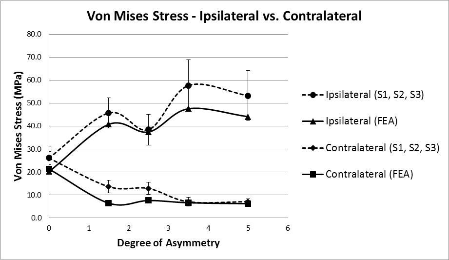
Principal stress values were calculated for the area of bone located directly beneath each strain gauge. The values for Young’s Modulus were taken from the FE tetrahedral elements located in the corresponding locations in the model, average values were calculated (Ipsilateral = 5.45GPa, contralateral = 5.34GPa). These values were then multiplied by the average principal strain values recorded during all tests (S1, S2, and S3), these values are quasi test results, being a combination of real strains and FE stiffness value. Figure 9 shows the Von Mises stress results calculated using these quasi test values, compared to the results from the FE model. At the baseline test reading of zero degrees a stress value of approximately 26MPa is present on both the ipsilateral and contralateral side; these stress values diverge as the degree of asymmetry increases with the contralateral side reducing to 7.1MPa and the ipsilateral side increasing to 57.7MPa at 3.5˚ asymmetry before reducing slightly to 53.2MPa.
The results of force vs. displacement tests and the strain data analysed thus far indicate that some sort of internal yielding is taking place. In order to explore this further the FE model was used to examine the Von Mises stress values for the trabecular volume underneath the vertebral laminae. On the ipsilateral side, at the maximum degree of asymmetry, values of 6.8 – 8.8MPa are computed, this is more than double the σyld value reported by Morgan & Keaveny [43] for yielding of vertebral trabecular bone indicating that the stress values are sufficient to cause yielding.
4.4. Principal Strain Direction
In order to better understand the mode/direction of loading as each step of asymmetry is applied the principal strain directions were analysed for specimen S2. This was done using the inverted 2D strain transformation equations in matrix form to initially calculate the values for Ɛx, Ɛy and gxy (Equation 3) where subscripts P, Q and R refer to the rosette gauge elements. These values were then used to calculate the principal strain angle using Equation 4.

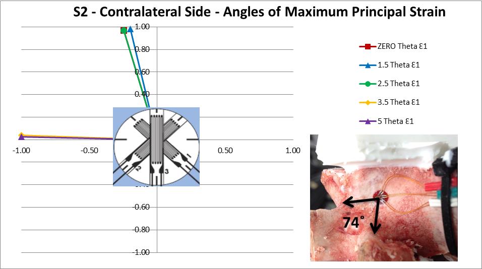
The principal strain direction on the ipsilateral side made little or no deviation in orientation as each step of asymmetry was applied. However, the contralateral side shows a sudden shift of 74˚ between the readings at 2.5˚ and 3.5˚ of asymmetry indicating a change in the deformation direction has occurred (Figure 10). This change in the principal strain direction is caused by 2 main factors, the physical change in loading brought about by the differing geometry at each step of asymmetry and the local yielding of the internal trabecular structure as discussed previously. An effect of this change in direction is that the vertebra is now loaded on a path which is different to the principal orientation of the trabeculae and osteonal structure of the bone, which could explain the sharp increase in strain between 2.5˚ and 3.5˚ of asymmetry.
5. Conclusion
The values for strain recorded in this study were broadly larger than the values reported in literature. However, the values reported in literature were recorded during sitting, walking and stair climbing. None of these motions involve deliberate hyper-extension of the spine; this is the first study to elucidate the relationship between loading due to hyperextension and strain, and the role of facet asymmetry.
In conclusion, tests were carried out to determine if and to what degree geometric asymmetry affects the difference in strain between the laminae on the ipsilateral and contralateral sides of the vertebra. These tests showed that as each subsequent step of asymmetry is applied there is an increase in both Von Mises stress and strain on the ipsilateral side, this increase has a complex non-linear progression; however pathological values for strain are recorded indicating potential damage, which is supported by the data.
An FEA model of the vertebra was created using µCT scans and published formulae linking bone mineralisation to material properties. This model was successful in replicating both the stiffness and strains that were measured during test.
Acknowledgements
This research is funded by the Irish Research Council under the Embark Award Scheme. Grant reference: RS/2012/318.
References
[1] J. W. Frymoyer, “Back pain and sciatica,” N. Engl. J. Med., vol. 318, no. 5, pp. 291–300, 1988. View Article
[2] R. N. Hensinger, “Spondylolysis and spondylolisthesis in children and adolescents,” J. Bone Jt. Surg., vol. 71, no. 7, pp. 1098–1107, 1989. View Article
[3] L. L. Wiltse, “Etiology of spondylolisthesis,” Clin. Orthop., vol. 10, pp. 48–60, 1956.
[4] J. H. Sutton, P. D. Guin, and S. M. Theiss, “Acute lumbar spondylolysis in intercollegiate athletes.,” J. Spinal Disord. Tech., vol. 25, no. 8, pp. 422–5, Dec. 2012. View Article
[5] P. Brunker, C. Bradshaw, K. M. Khan, S. White, and K. Crossley, “Stress Fractures A Review of 180 Cases,” Clin. J. Sport Med., vol. 6, pp. 85–89, 1996. View Article
[6] D. W. Jackson, “Spondylolysis in the female gymnast,” Clin. Orthop. Relat. Res., vol. 117, pp. 68–73, 1976. View Article
[7] L. Swärd, M. Hellström, B. Jacobsson, and L. Peterson, “Spondylolysis and the Sacro-Horizontal Angle in Athletes,” Acta radiol., vol. 30, no. 4, pp. 359–364, 1989. View Article
[8] C.-W. Toueg, J.-M. Mac-Thiong, G. Grimard, S. Parent, B. Poitras, and H. Labelle, “Prevalence of spondylolisthesis in a population of gymnasts,” Stud. Health Technol. Inform., vol. 158, pp. 132–137, 2010. View Article
[9] W. J. Beutler, B. E. Fredrickson, A. Murtland, C. A. Sweeney, W. D. Grant, “The natural history of spondylolysis and spondylolisthesis: 45-year follow-up evaluation,” Spine (Phila. Pa. 1976)., vol. 28, no. 10, pp. 1027–1035, 2003. View Article
[10] C. H. Crawford, C. G. T. Ledonio, R. S. Bess, J. M. Buchowski, D. C. Burton, S. S. Hu, B. S. H. Lonner, D. W. Polly, J. S. Smith, and J. O. Sanders, “Current Evidence Regarding the Etiology, Prevalence, Natural History, and Prognosis of Pediatric Lumbar Spondylolysis: A Report from the Scoliosis Research Society Evidence-Based Medicine Committee,” Spine Deform., vol. 3, no. 1, pp. 12–29, 2015. View Article
[11] H. Crewe, “Lumbo-pelvic loading during fast bowling in adolescent cricketers: The influence of bowling speed and technique,” J. Sports Sci., vol. 31, no. 10, pp. 1082–1090, 2013. View Article
[12] P. T. Annear, T. M. H. Chakera, D. H. Foster, P. H. Hardcastle, “Pars Interarticularis Stress and Disc Degeneration, Cricket’s Potent Strike Force: The Fast Bowler,” ANZ J. Surg., vol. 62, no. 10, pp. 768–773, 1992. View Article
[13] D. W.Jackson, “Stress reactions involving the pars interarticularis in young athletes,” Am. J. Sports Med., vol. 9, no. 5, pp. 304–312, 1981. View Article
[14] H. Hoshina, “Spondylolysis in athletes,” Phys Sport. Med., vol. 8, pp. 75–9, 1980.
[15] J. J. Rankine and R. a Dickson, “Unilateral spondylolysis and the presence of facet joint tropism.,” Spine (Phila. Pa. 1976)., vol. 35, no. 21, pp. E1111-4, Oct. 2010. View Article
[16] Y. M. Masharawi, “Lumbar Facet Orientation in Spondylolysis: A Skeletal Study,” Spine (Philadelphia, Pa. 1976), vol. 32, no. 6, pp. E176–E180, 2007. View Article
[17] S. C. Cowin, Bone mechanics handbook, 2nd ed. CRC press, 2001. View Book
[18] L. E. Lanyon, W. G. Hampson, a E. Goodship, and J. S. Shah, “Bone deformation recorded in vivo from strain gauges attached to the human tibial shaft.,” Acta Orthop. Scand., vol. 46, no. 2, pp. 256–68, May 1975. View Article
[19] L. Cristofolini, N. Brandolini, V. Danesi, M. M. Juszczyk, P. Erani, and M. Viceconti, “Strain distribution in the lumbar vertebrae under different loading configurations.,” Spine J., vol. 13, no. 10, pp. 1281–92, Oct. 2013. View Article
[20] S. Gilchrist, P. Guy, and P. a Cripton, “Development of an inertia-driven model of sideways fall for detailed study of femur fracture mechanics,” J. Biomech. Eng., vol. 135, no. 12, p. 121001, 2013. View Article
[21] J. S. Shah, W. G. Hampson, and M. I. Jayson, “The distribution of surface strain in the cadaveric lumbar spine.,” J. Bone Joint Surg. Br., vol. 60–B, no. 2, pp. 246–251, 1978. View Article
[22] A. G. U. Sawa and N. R. Crawford, “The use of surface strain data and a neural networks solution method to determine lumbar facet joint loads during in vitro spine testing.,” J. Biomech., vol. 41, no. 12, pp. 2647–53, Aug. 2008. View Article
[23] J. A. Szivek, R. F. Roberto, and D. S. Margolis, “In Vivo Strain Measurements from Hardware and Lamina during Spine Fusion,” J. Biomed. Mater. Res. B. Appl. Biomater., vol. 75B, no. 2, pp. 243–250, 2005. View Article
[24] Y. Kuo and J. Wang, “Strain analysis of pars interarticularis and its implications in the spondylolysis rehabilitation strategies,” Biomed. Eng. Appl. Basis Commun., vol. 19, no. 2, pp. 79–84, 2007. View Article
[25] D. R. Carter, B. R. Blenman, and G. S. Beaupré, “Correlations between mechanical stress history and tissue differentiation in initial fracture healing,” J. Orthop. Res., vol. 6, no. 5, pp. 736–748, 1988. View Article
[26] H. M. Frost, “On our age-related bone loss: insights from a new paradigm.,” J. Bone Miner. Res., vol. 12, no. 10, pp. 1539–1546, 1997. View Article
[27] J. P. Dickey, G. A. Dumas, D. A. Bednar, and N. Sciences, “Comparison of porcine and human lumbar spine flexion mechanics,” Vet. Comp. Orthop. Traumatol. Archive. vol. 16, no. 1, pp. 44–49, 2003. View Article
[28] R.-M. Lin, “Distribution trabecular and regional strength of bone in the porcine lumbar Proximal,” Clin. Biomech., vol. 12, no. 5, pp. 331–336, 1997. View Article
[29] A. Kettler, L. Liakos, B. Haegele, and H.-J. Wilke, “Are the spines of calf, pig and sheep suitable models for pre-clinical implant tests?,” Eur. Spine J., vol. 16, no. 12, pp. 2186–92, Dec. 2007. View Article
[30] D. Taylor, L. Mulcahy, G. Presbitero, P. Tisbo, C. Dooley, G. Duffy, and T. C. Lee, “The Scissors Model of Microcrack Detection in Bone: Work in Progress,” MRS Proceedings, vol. 1274, 2010. View Article
[31] R. K. Wilcox, “The influence of material property and morphological parameters on specimen-specific finite element models of porcine vertebral bodies.,” J. Biomech., vol. 40, no. 3, pp. 669–73, Jan. 2007. View Article
[32] R. Schmidt, M. Richter, L. Claes, W. Puhl, and H.-J. Wilke, “Limitations of the cervical porcine spine in evaluating spinal implants in comparison with human cervical spinal segments: a biomechanical in vitro comparison of porcine and human cervical spine specimens with different instrumentation techniques.,” Spine (Phila. Pa. 1976)., vol. 30, no. 11, pp. 1275–82, Jun. 2005. View Article
[33] E. Tanck, J. Homminga, G. H. van Lenthe, and R. Huiskes, “Increase in bone volume fraction precedes architectural adaptation in growing bone.,” Bone, vol. 28, no. 6, pp. 650–4, Jun. 2001. View Article
[34] B. M. Cyron, W. C. Hutton, J. D. Troup, “Spondylolytic Fractures,” J. Bone Jt. Surg., vol. 58–B, no. 4, pp. 462–466, 1976. View Article
[35] B. M. Cyron, W. C. Hutton, “The Fatigue Strength of the Lumbar Arch in Spondylysis,” J. Bone Jt. Surg., vol. 60–B, no. 2, pp. 234–238, 1978. View Article
[36] D. W. Wagner, D. P. Lindsey, and G. S. Beaupre, “Deriving tissue density and elastic modulus from microCT bone scans,” Bone, vol. 49, no. 5, pp. 931–8, Nov. 2011. View Article
[37] H. Cao, J. L. Ackerman, M. I. Hrovat, L. Graham, M. J. Glimcher, and Y. Wu, “Quantitative bone matrix density measurement by water- and fat-suppressed proton projection MRI (WASPI) with polymer calibration phantoms,” Magn. Reson. Med., vol. 60, no. 6, p. 1433, 2008. View Article
[38] L. Feng, M. Chittenden, J. Schirer, M. Dickinson, and I. Jasiuk, “Mechanical properties of porcine femoral cortical bone measured by nanoindentation.,” J. Biomech., vol. 45, no. 10, pp. 1775–82, Jun. 2012. View Article
[39] J. D. Currey, “Effects of differences in mineralization on the mechanical properties of bone,” Philos. Trans. R. Soc. London, vol. 304, no. 1121, pp. 509–518, 1984. View Article
[40] T. J. Vaughan, C. T. McCarthy, and L. M. McNamara, “A three-scale finite element investigation into the effects of tissue mineralisation and lamellar organisation in human cortical and trabecular bone.,” J. Mech. Behav. Biomed. Mater., vol. 12, pp. 50–62, Aug. 2012. View Article
[41] World Health Organization. "WHO scientific group on the assessment of osteoporosis at primary health care level." Summary meeting report. 2004. [Online]. Available: http://www.who.int/chp/topics/Osteoporosis.pdf. View Report
[42] N. Kelly and J. P. McGarry, “Experimental and numerical characterisation of the elasto-plastic properties of bovine trabecular bone and a trabecular bone analogue.,” J. Mech. Behav. Biomed. Mater., vol. 9, pp. 184–97, May 2012. View Article
[43] E. F. Morgan and T. M. Keaveny, “Dependence of yield strain of human trabecular bone on anatomic site,” Jounral Biomech., vol. 34, pp. 569–577, 2001. View Article